1. Inductive Sensors Work
Inductive sensor consists of three parts: oscillator, switch circuit, and enlarged output circuit. Oscillator to generate a alternating magnetic field. When the metal object close to the magnetic field, and to achieve sensing distance, in the metal target to generate eddy current, causing oscillation damping, and even stop vibration. Oscillator stopping oscillation and vibration level after the change has been processed and converted into amplifier switch signal, trigger-driven control device, so as to achieve non-contact type of testing purposes.
2. Sensor Selection Guide
On the basis that the right to decide which one is the principle sensor. It depends on the objectives to be measured material.
If the target is metal, you need an inductive sensor.
If the target is made of plastic, and paper to do; or (oil-based or water-based) fluid, particle, or powder, you need a capacitance sensor.
If the target with a magnetic, electromagnetic sensors it is appropriate.
The application for you to choose the best sensor of four steps:
Step 1 according to shell shape
Step 2 Press the action from the
Step 3 according to the form of electrical data and output
Step 4 Press the other technical parameters
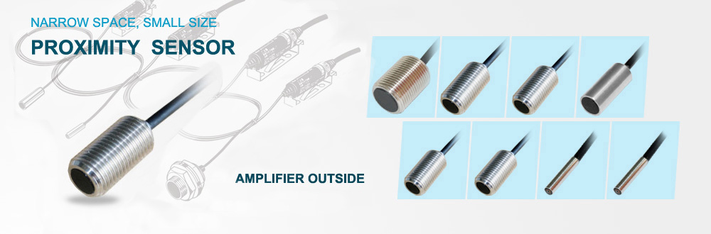
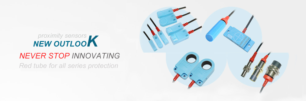
Step 1 according to shell shape
Cylindrical sensors
This is the front of the sensors in them a sense region, pointing axis. The diameter is available from 3mm (not thread) and 4mm (with thread), until / / the existing casing materials are:
★ High Stainless Steel
★ brass, nickel plated or covered with PTFE
★ Plastic
Rectangular sensor
Slot Sensors
Step 2 Press the action from the
Operating distance is close to the switch of the most important features. According to physical principles, for the inductive sensor and capacitive sensors, can be applied to the following approximate formula:
S ≤ D / 2
The formula, D is the sensor's sensing face diameter.
S is the sensor moves away from
Action from the definition of
When using a standard test plate axial proximity switch sensing surface, so that when the switch changes the output signal switch sensor surface and measured the distance between the test board.
Standard test board size:
The side length or diameter of the sensor, or 3Sn (3 times the rated movement distance), whichever is greater, thickness of 1mm
Material: carbon steel for the ST37 or
For example: D = 18mm diameter sensors
Sn = 5mm
Then D (18mm)> 3Sn (3X5mm = 15mm)
Taken as the standard test board 18X18X1
Such as the diameter D = 18mm
Sn = 8mm
Then D (18mm) <3Sn (3X8 = 24mm)
Then D (18mm) <3Sn (3X8 = 24mm)
Taken as the standard test board 24X24X1
Rated Operating distance Sn
Switch design moves away from the ideal, that does not consider manufacturing and deviations caused by external conditions.
Effective action from the Sr
Switch at the rated voltage and room temperature (23 ± 50 ℃) measured movement distance
0.9Sn £ Sr £ 1.1Sn
Available actions from the Su
Switch to allow the ambient temperature -25 ℃ - +70 ℃, the input voltage at the rated voltage of 85% to 110%, the measured distance from the action
0. 9Sr £ Su £ 1.1Sr
Reliable action from Sa
Distance in this action, the action switches are reliable
0 £ Sa £ 0.81Sn
Repeatability
Is the temperature in the shell (23 ± 5) ℃, relative humidity was random, power supply voltage Ue ± 5%, in 8 hours to measure the extent arising from the variation of effective distance:
R £ 0.1Sr
Loop width of the H
When the test board near the close to the switch and leave the proximity switch when the test plate obtained when the distance between the two switching points difference. The distance difference is relative to the effective distance of the percentage of that measured ambient temperature (23 ± 5) ℃, and the rated working voltage range:
H £ 0.2Sr
Operating distance measurement, the standard test panels must be axial proximity switches, however, if the test plate lateral movement in the effective sensing area, the action will be different from, and with the distance from the axis.
For slot sensors, response and target only the depth of insertion notch.
Attenuation coefficient
Factors that affect the movement distance
Attenuation (or damping) the nature of the material played an important role, which can be used to describe the attenuation coefficient.
Attenuation coefficient is a material moves from one relative to the ST37 steel is to reduce the number. Attenuation coefficients are smaller, the materials for a particular action from the smaller.
Characteristic parameters for the capacitive sensor is a relative dielectric constant
Flush / non flush-mounted
Flush equipment: sensors embedded in metallic base, the working surface of the effective sensing surface is flush with the base.
Non-flush-mounted: Sensor is not buried within the base from the property, their effective induction to the work surface to maintain a certain size with Block. The maximum possible movement distance (and the diameter of the) is a non-flush sensors to obtain.
Flush installation of inductive sensors and capacitive sensors have these advantages: they have better mechanical protection properties, and non-flush mounted sensors, compared to the error affected the sensitivity of lower electricity. These are within the mask by a special ring to get.
Flush installation of sensors and non-flush mounted sensors compared to its role in a distance of about 69% of the latter.
Sensors often rely on a first one to be installed. In order to avoid mutual interference, should be kept from the table given in the minimum clearance C.
Step 3 Press the electrical data and output type
DC wire
Load must be connected in series within the sensor to work.
Short circuit protection and polarity protection transformation.
DC 3-wire
These sensors separate power supply and load connections. They have overload protection, short circuit protection and polarity protection, and their residual current is negligible.
DC four-wire
These sensors with the same three-wire system, but also to provide a normally closed and a normally open output.
AC wire
Load must be connected in series in the sensor to work. According to its function, in the case of switching off, there will be a small residual current off. When it will have a voltage drop.
Type II wire NAMUR
NAMUR sensor oscillator is simply a second-line system contains a sensor. The sensor's resistance with the sensor target distance, and change, the corresponding current is changed also.
Parallel and series connections
Proximity switches can be used in parallel or series connection, in order to achieve a simple logic functions (AND, or, NAND, or).
Combined with the mechanical switch is possible. According to anti-riot provision, NAMUR sensors can not be used in parallel or series connection.
Three-and four-wire DC sensors in series DC
When the series, the voltage drop added to a single sensor connected to extension of time to add
Three-and four-wire DC-DC Shunt Sensor
Two-sensor series sharing
Normally open contact: "and" logic
Normally closed contact: "or" logic
When connected in series, the voltage drop in the sum of the sensor, which reduced the load on the available voltage, so pay attention: not less than the minimum load voltage (note grid voltage fluctuations).
Mechanical switches and sensors in the parallel exchange
The contact broke off the sensor supply voltage, if the sensor is attenuated by mechanical contact closure period, then the function will produce a short-term failure, sensor preparation delay time (t £ 80ms ) avoid the immediate on-off action.
Compensation Methods: one resistor in parallel with mechanical contacts on the (disconnected when the contact is the same), this resistance to the sensor will not work preparation time, with 220V AC, this resistance is about 82kW/1w.
Resistance calculation: approximation about 400W / V
Two-sensor parallel exchange
Normally open contact: "or" logic
Normally closed contact: "and not" logical
When the parallel, the residual current add, for example: it can -
- In the programmable controller input will produce a high illusion.
- More than a small relay to maintain current, to avoid the drop in contact.
- Mechanical switch in parallel with the exchange of sensor
Closed contact to the sensor circuit voltage, when the contacts break, the only delay in the preparation (t £ 80ms) after the sensor was in a functional state of readiness.
Remedies: a resistor in series with contacts can be reliably guaranteed minimum operating voltage of the sensor, thus avoiding mechanical contact disconnect delay after the preparation.
Resistance calculation formula: R =
Step 4 Press the other technical parameters
No-load current I is the current sensor needs its own, that in the absence of load measurement.
Operating current (continuous current) I is the maximum continuous work load current.
Transient current I refer to is closed will not damage the bureau of the short time allowed in sensor current.
Residual current I is the sensor disconnected, the current flowing through the load
Operating voltage U is the supply voltage range. In this voltage range, sensors can guarantee security. For NAMUR sensors, must be marked rated voltage.
U is the voltage drop in the sensor when the sensor connected to the second side or the measured output voltage.
Ripple voltage is the voltage superimposed on the AC voltage (peak - peak), commonly used arithmetic mean expressed as a percentage.
Switching frequency is the transition from decaying to a state of transformation does not decay the maximum number of hertz (Hz) to measure.
Allow interference in the power supply voltage is the role of the short voltage spikes can damage unprotected sensor.
Connect delay is close to the switching power supply connected to the proximity switch to work, the time needed.
Pulse inhibition of the error
When working voltage plus the time in TV this time period, the inhibition of the error signal output.
Short-circuit protection
If the current exceeds the limit, then the output will be periodically closed and released until the short is removed.
Polarity protection
DC sensor power supply with input voltage polarity to prevent the erroneous connection of the protection.
Overload Protection
There was no any overload damage to the sensor
Circuit protection
Power line circuit will not cause malfunction
The form of color-coded wires and connections
Form functional level of wire color / terminal
2 - Line N.O. free
AC N.C. free
or N.O. marked L + brown, L-Blue
DC N.C. marked L + brown, L-Blue
The exchange of metal shell be ground-based sensors
Note: Electrical connection diagram of BI-BN-Brown Blue WH-White BK-Black